PicDongle 12A Series users' guide
Installing PicDongle 12A Digital Sampling System
The PicDongle 12A series are multichannel data acquisition modules for use with any PC or other computer with a RS232-E serial port interface. The PicDongle is controlled by a low-power RISC microcontroller and requires no handshaking with the host PC. Data is transmitted to the host PC as a constant stream with a frame marker. The frame marker is two bytes of FFh. The A/D sampled data following the frame marker is low byte then high byte for each channel starting with channel 1. After all 8 channel samples (16 data bytes) are sent a new frame marker is transmitted. The host PC controls the data stream with the RTS line. Setting RTS 'high' or +3 to +15 Volts (logic '0' for the RS232) starts the stream and a 'low' stops the stream.What the PicDongle Digital Sampling System Contains:
Windows/DOS/C Starter Code diskettePicDongle 12A Series hardware
What You Need to Get Started:
1. An IBM-PC or compatible computer equipped with at least one 3 1/2" 1.44 Mbyte floppy disk drive or other computer that can read a IBM-PC 1.44 MByte floppy.If you want to run the example software you will need:
2. Windows 3.x, 95 or PC/MS-DOS 5.0 or later disk operating
system, and
3. Input Transducer: Sensor or Signal source or laboratory test
signal generator
For advanced use of this and other SiliconSoft Digital Sampling Systems, programmer support for Window DLLs, C, C++, OS/2 and DOS is available.
Installing the Example Digital Sampling Software
Please read the README.TXT file to check for the latest update about PicDongle Digital Sampling before you begin installation of the Digital Sampling System.Making a Copies of the Program Diskettes
The SiliconSoft PicDongle Digital Sampling example software is not copy-protected, so you can make backup or archive copies.
Software Installation Process:
To install PicDongle Digital Sampling Software on your computer follow the steps below:While you are in Windows, change to the drive that contains the SiliconSoft Digital Sampling diskette. If you are using the Program Manager, select File Menu and choose Run. Then type (for example if diskette is in drive A):
A:SETUP.EXE
and press Enter.
Follow the instruction displayed on the screen.
Installation of the SiliconSoft Digital Sampling Hardware:
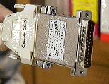
Select a COM port (normally the PC COM port connector is a DB25 plug).
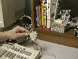
Connect the COM port cable to the PicDongle (refer to the labels on the PicDongle casing). To verify operation, start the example windows program and select the COM port you are using. While recording, touch pin 1 with a metal object. You should see the channel 1 indicator pick up a 60 Hz signal.
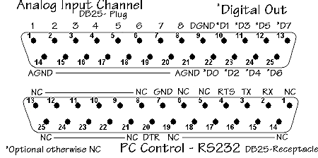
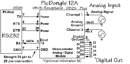
To make a connection to the PicDongle be sure to read the bottom label and note the signal and ground pin numbers. Solder your wires to a DB25 receptical connector (pin 1 is channel 1, pin 2 is channel 2, etc., and pin 14 is ground). If the COM port is reset, the PicDongle's LED should be lit when the PC is on.
Signal source connection to Pic Dongle
Pic Dongle interface to host PC
Connection to serial port with DB-25 pin connector
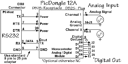
Connection to serial port with DB-9 pin connector
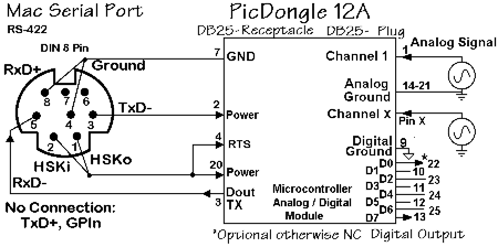
Connection for Macintosh port
Warning Note:
While the PicDongle is a robust design with fault condition protection for excess input voltages, as any electronic device, it can be damaged if it is misused or misapplied.
For your protection and to prevent possible hardware damage - Turn off the power to your computer and any attached peripherals before continuing if you are not certain about the operation and use of the hardware you are using. Be sure to only use properly grounded AC line operated equipment. Do not use or connect together by cable any equipment that ungrounded and AC line operated. The PicDongle hardware is protected for over full scale input voltages (-0.5 V to 5.0 V or 10 mA maximum) but be aware that the DB cable connectors shells and shields and PicDongle chassis grounds are all connected to the common PC's chassis ground. If you have a noisy ground environment and low level signals you may want to use the inputs in a differential mode. That is, use one channel for the signal input and use the next channel to measure the ground voltage. Subtract the ground voltage value from the signal voltage to get the true signal value. Since the channel to channel sampling skew is a few microseconds, the noise subtraction works for frequencies up to ten KHz or more.
1. Plug the PicDongle 12A digital sampling hardware directly into the desired serial port.
2. Turn on the power to your PC and any attached peripherals.
3. Start the example software or other COM or TERMINAL software and configure the hardware setup to 8 bits, No parity, 1 Stop bit at a 19,200 bps.
When you select the port to which the PicDongle is connected and select Connect in the Dialog Box, you should see the data stream start. Normally the power required to operation the PicDongle is obtained from the RS232-E serial port. Some laptop or palmtop PC's may not have a standard power serial port and the PicDongle will not operate correctly. The LED should be lit on the PicDongle after it has been connected to a COM that has been reset (normally it's reset upon bootup) and it will stay on unless you toggle DTR 'high'.
Use of the PicDongle 12A Hardware:
The PicDongle 12A does not require any custom programming at the host PC. You can use any standard terminal program to view or capture the data stream from the PicDongle. However, if you want to directly control the data stream within your custom programm, see the PicDongle 12A Windows C example. While the example source code is for a C program compiled for Windows, it gives you enough information for use with other languages or computers with standard COM port support.The TTY Windows C sample program and source code is for use with Microsoft Visual C environment. This sample program demonstrates how to receive data from the PICDongle12A hardware using the COMM API. This program will accept data through the COM port from the PICDongle12A module.
Install the PicDongle 12A by attaching it to any unused Serial port on you computer as covered in the previous pages. Run the TTY.exe sample program in Windows 3.1 or Windows 95. A window will be displayed with a menu bar with "Action", "Settings", and "About" menu items.
1) Click on the Setting menu item to display the settings dialog box. Select the COM port of where the PicDongle 12A is attached. Check to make sure that the other settings are set as follows:
Baud Rate: 19.2k Data Bits: 8 Parity: None Stop Bits: 1 Flow Control: None (all boxes are NOT checked). Also check the "Use CN_RECEIVE Notifications" box. Then press the OK button to save settings and remove dialog box.
2) Click on the "Actions" pulldown menu item. Then click on the "Connect" item to start receiving data from the PicDongle 12A hardware. Click on the "Disconnect" item in the "Actions" pull down menu to stop receiving data.
3) The data from the PicDongle 12A will be displayed in the TTY.exe Window in HEX format. The frame markers are also displayed.
Example of output: