PicDongle 12A Series connection guide
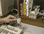
Select a COM port.
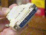
Note: Normally the PC COM port connector is a DB25 plug.
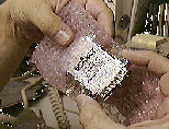
Remove the PicDongle from the packaging.
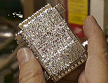
Position the PicDongle for connection.
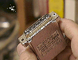
Note how the PicDongle connects to the PC host from the DB25 receptacle.
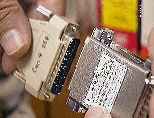
Insert the PC's cable plug into the PicDongle receptacle.
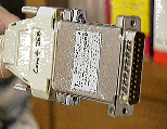
To verify operation, start the example Windows program and select the COM port you are using.
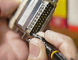
While recording, touch pin 1 with a metal object. You should see channel 1 pick up a 60 Hz signal.
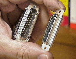
To make a connection to the PicDongle, use a DB25 connector. Be sure to read the bottom label and note the signal and ground pin numbers.
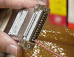
Solder a wire to pin 1 of the connector for channel 1, and solder another wire to pin 14 for signal ground.
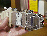
Solder additional wires if you want more channels and assemble the shell halves.
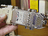
If the COM port is reset, the PicDongle's LED should be on when the PC is on.
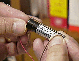
You can check the operation by connecting a 1.5V battery to the PicDongle input. Note the PicDongle measures 0 to +4.095V so apply the positive voltage to pin 1. Use the example program or a terminal COM program to read the voltage.